
Info:
- Although I had been thinking about it for several months the first commitment was to purchase a second hand Toyota Prius EPS in July 2021, via Trade Me, for $200. Little did I know the complexity of the task and the costs to come!
2. A very good article from a Mustang site (https://www.vintage-mustang.com/threads/electric-steering-with-fail-safe-no-ebay-module-needed-pics-videos.1008722/) gives a heap of information which led to going with the Toyota Prius unit. It has steel gears and a default mode when no input to the ECU re road speed. Some units require this information to function.
3. Peter at Connett Engineering fabricated the three components that I designed, with advice from him. The cost was over $3000, but this included remaking one part that had a design error. Also included machining splines on the cut steering column for the new spline clamp.
4. The whole process was three times more complicated because of my desire to use the original steering wheel and horn and indicator hub. This meant designing and building a slip ring to convey the 4 electric cables and also a centring system to keep the indicator lever upright in the Horn hub. Otherwise it would simply rotate with the steering wheel and there would be no indicator cancelling mechanism.
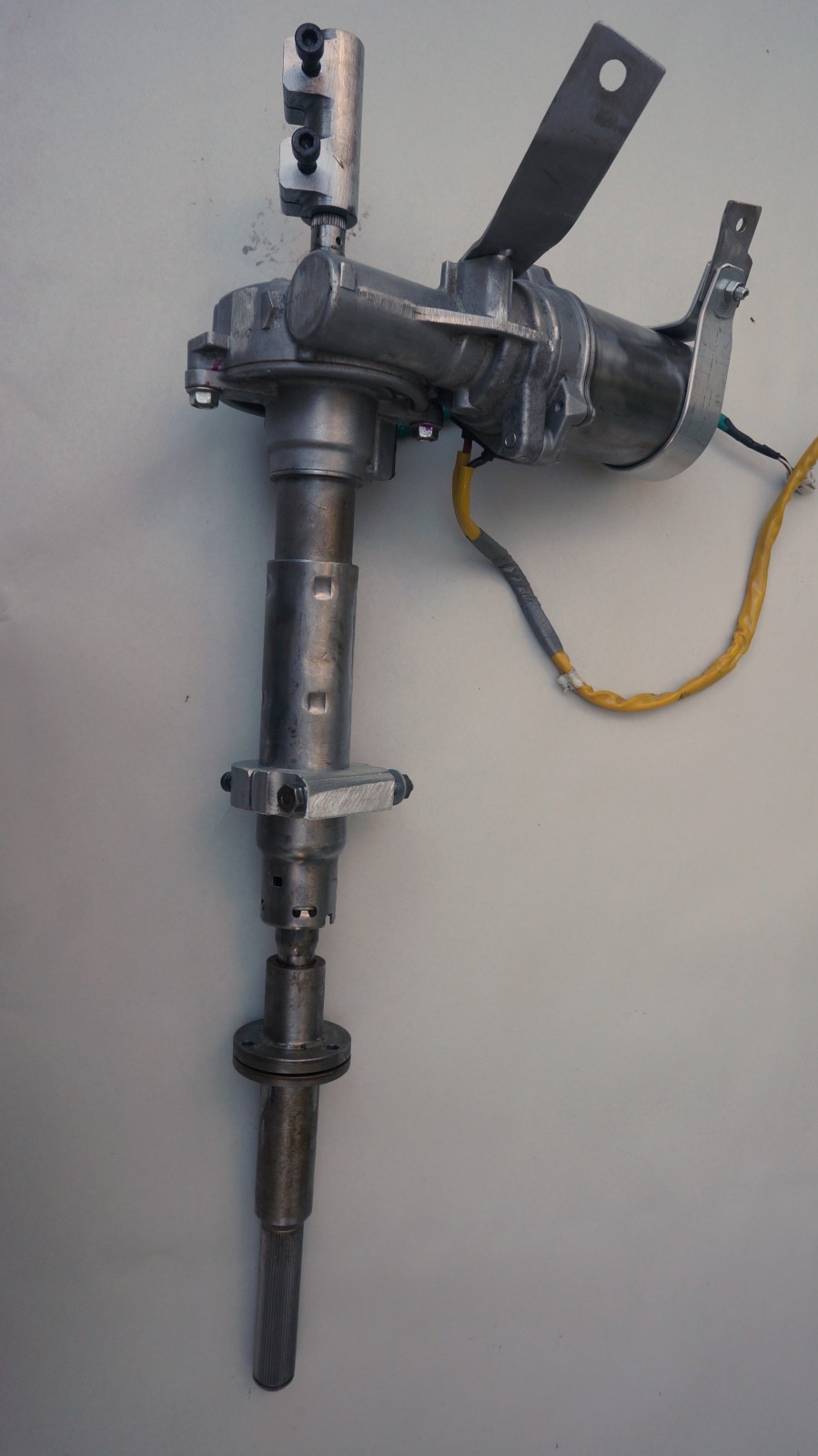
5. Through contacts, I manged to obtain a spare steering column from a Christchurch SP250 owner who had removed his for a rack and pinion conversion. However I wanted to keep my original steering wheel, which was fitted to a variable length splined shaft of which Neil Kruze was very proud. It gives some adjustment to the length which helps with the slip ring design.
6. I considered the two LVV inspectors available in Taranaki and decided to work with Steve Hildred. He forewarned me that the cost started at $800. Overall, he has been OK to work with and outlined the need for very specific steering column clamps and a high quality of workmanship.
7. Many photographic images taken, which was just as well because Steve Hildred wanted everything documented.
8. Centring system for horn hub. Involves two sets of pulleys (2×10 teeth and 2x 24 teeth) with one common shaft, bearing mounted and stood out 60mm from the steering column. Two belts (44 teeth and 30 teeth, cut from a 16mm belt from the aquabike project) connect the two matched sets of pulleys. Pulley 4 is fixed to the steering column housing and does not rotate. By the attachments the belts hold the horn hub pulley from rotating as the steering wheel column turns around it. The outcome has been very pleasing.
9.
- Slip ring . Electrical continuity for the four wires emerging from the horn hub is as follows.
Horn hub wire colour code
Horn +ve Green (Constant live, horn button to earth circuit)
Indicator +ve Green with Brown stripe (Constant Live)
Indicator Left Green with Red stripe
Indicator Right Green with White stripe
The horn wire and indicator +ve are live.
The current transits through the rotating steering column through 4 3mm nylon lined holes to continuous contact with 4 internal and external brass sleeves via 12mm expansion pins from a watch strap repair kit. They are placed in position via a 4 mm screw hole, then the screw is advanced until the tip is flush with the brass sleeve. I expect some wear from the uneven holes so the pins may need to be replaced from time to time.
10. Ancillary to project Front bumper removed. Number plate trimmed and set on cut off bumper supports in optimal position. Steering wheel cleared, restored, and painted. Horn hub dismantled, cleaned, repaired and reassembled. Vin transponder fitted.
