BUILDING TIPS AND SHORTCUTS
Cutting Out
A vast number of parts need to be cut accurately to size. Two good techniques for this: photocopy plans to paper, cut to the line then glue to aluminum with glue stick. Cut to the line on your band saw, using magnifying safety glasses. Alternative, purchase excess 1mm (0.040in) polycarbonate ( used for turtle-deck), lay over plans and trace outline onto the clear with marker pen. Cut to size and use as a stencil. Good for multiple parts. Also a good way to counter-transfer holes (ie where can’t access guide hole to transfer location).
Klegecell alignment holes
Alignment holes in Klegecell ribs – use a short length of brass tube of correct outside diameter (say 4mm). Taper the outside edge to a sharp profile with sandpaper, while rotating in drill press. Then file an exit port about 5mm from the cutting end, as for a hole punch. Rotate in drill press to cut a clean hole of perfect diameter for guide screws and wires prior to machining the outside profile of the ribs.
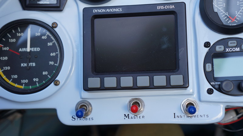
3. Instrument panel
Consider a Dynon 10A EFIS (https://www.dynonavionics.com/) for main instrument. Weighs much less than conventional instruments and includes G metre, VSI and compass. Also has transponder feed – if you need one of these in your airspace.
Priming the carburetor
My mentor, Nev, achieves this by pressurising the fuel tank by blowing down the vent tubing, clamping the end of the tube, then release the carb pump cover screw. Fuel flows freely up the line.
Taking this further, I have dismantled the carb pump (here is a good web site with photos) Fabricate an elbowed lever to pass through the vent hole to depress the metal centre of the diaphragm that controls fuel flow through the pump.
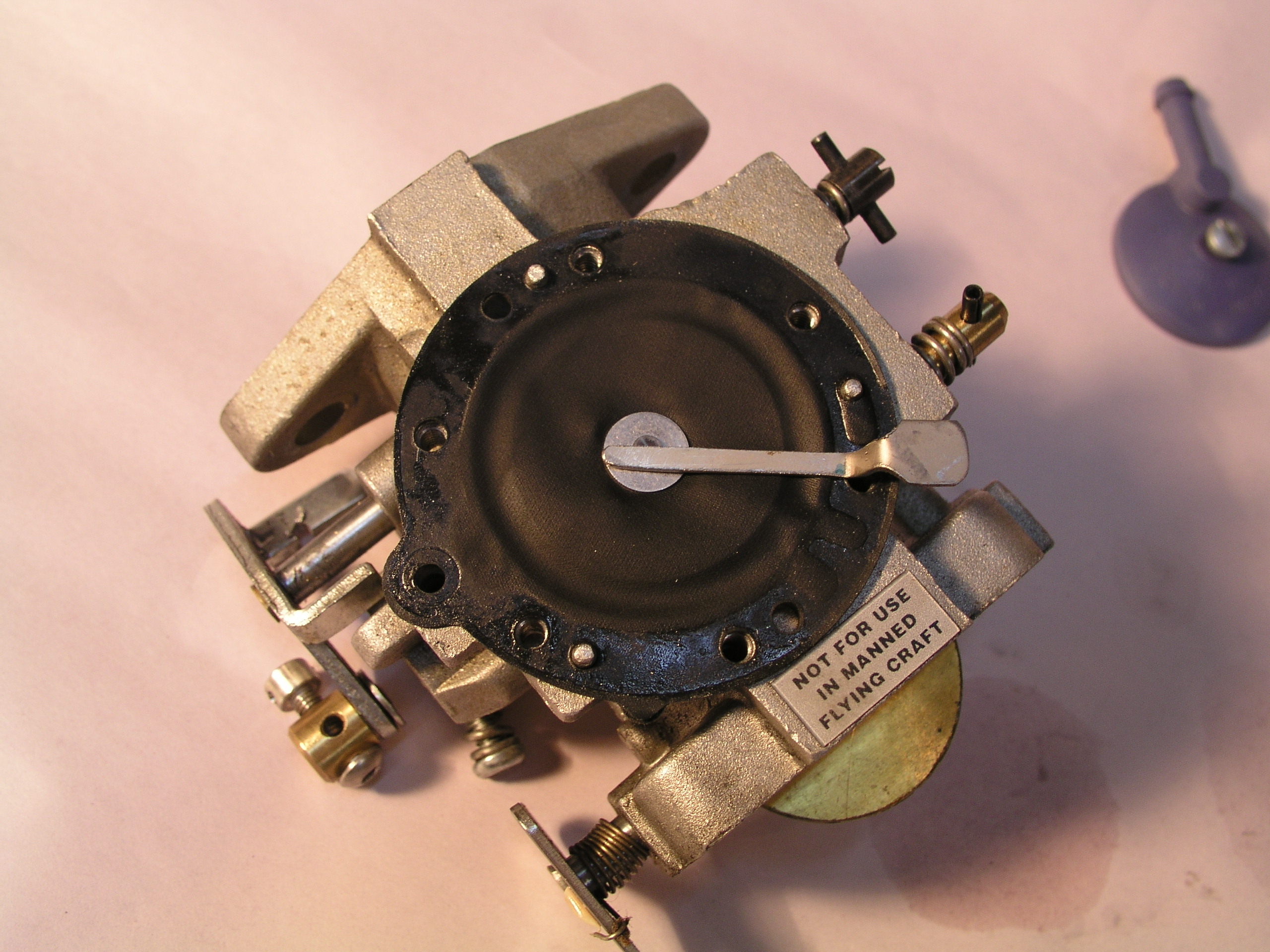
In essence the fabricated tab opens the fuel pump’s output control valve to maximum output, and the pump can draw several cc’s of fuel along the fuel line with each engine rotation. Even better, by pressurising the
fuel tank (by blowing down and clipping the breath line) the fuel flows straight through the carburettor when the tab is depressed, without even turning the engine.
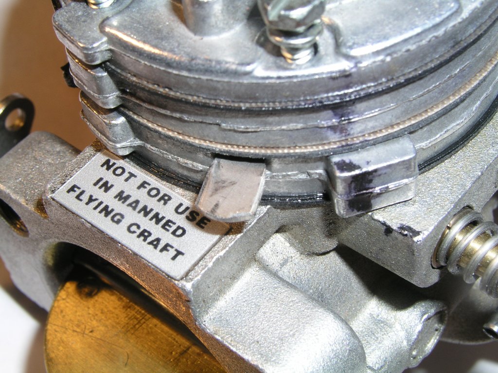
5.Venting of the fuel pumps atmospheric vent to the carburettor inlet. This involves sealing the external vent with Silicone and drilling a 3mm hole through the carb body and into the carb inlet. There is a casting nipple to guide the way.
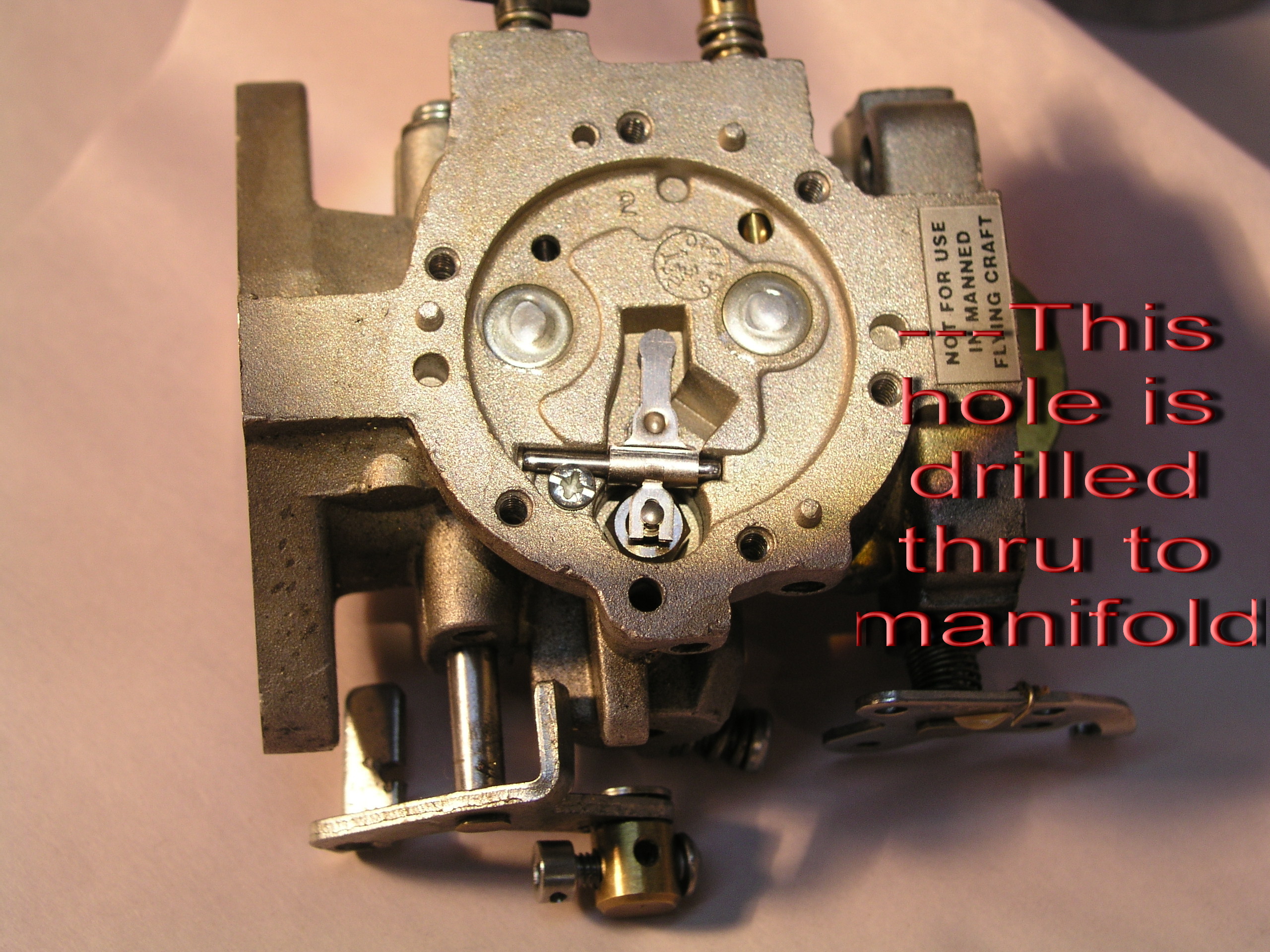
The process is described in Michel Colomban’s handbook on engine care. Photos show dismantled carb pump, installed lever to open the fuel valve, and location of hole to drill to divert venting of pump to carb inlet. The space around the lever is occluded with silicone.
6. Project planning
Try to do something every day on the project, even if just sweeping the floor. Get friends round to go over progress – if they can stand it again! Their visits can help keep you inspired.
7.Lathe
Buy a small lathe and teach yourself the basic skills. I regard a lathe as essential and one of the really enjoyable parts of the project. There are dozens of parts whose fabrication benefits from basic machining.
8.Do heat the Klegecell
You can purchase Klegecell already heat stabilised, otherwise this definitely needs to be done, as advised in the plans. I measured a shrinkage of 10% at 70 degrees C. Might be enough to de-bond your wings on a hot day flying! It’d be like Icarus!
9. Metric / Imperial
Mixing both systems works fine. Far better to fabricate using metric. All aluminium sheet is sized in equivalent metric and imperial. AN hardware is best for price and range. Metric bolts required a lot of cutting threads to size. For small fasteners you can buy nice stainless 4mm screws with cap head or button head and they conveniently fit 8-32 nut-pates. I have used these 4mm ss screws for all cover plates, wheel pants – everywhere non structural.
10. Modificationsto Cricri plans
Here is a list of the modifications I have made:
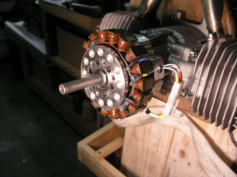
-3w engines
-Spherical bearing to upper and lower rudder pivot points
-Access hatch on front upper fuselage
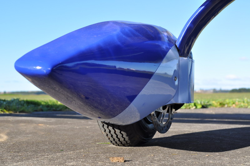
-Undercarriage faring secured by two nut-plates – removable
-Bend in ss rods attaching fuel tank to fuselage
-Circuit breakers (x7)
-Klegecell / fibreglass frames forward and aft of canopy (instead of Ali)
-Polyurethane to seal visible Klegecell stiffeners in fuselage (aesthetics only)
-Split automotive conduit to convey fuel lines and wires through front fuselage
-Dynon 10A EFIS instead of conventional flight instruments
-6mm nut-plates to receive 6mm the two elevator bolts (very difficult to fit conventional nuts)
-Hydraulic disc brakes and split hose from a single Shimano lever
-Embroidery in seat cover
-Nose-cone flared to receive winglets of engine nacelles
-Tinted primer paint for fuselage (aesthetics only) – canopy raised 50mm to fit pilot Can’t think of anything else but probably lots of small alterations.
11. Supplies If you can acquire a list of sources and sizes of material used this can be hugely helpful to the project. Of course I have such a list – mostly New Zealand Suppliers – some French, some US.I will make this spreadsheet available for a limited time, here.
12. Fettling & Fiddling Coined from another author, this is a process I love. Continued small incremental refinements until you get the thing working just right – to your satisfaction. Failures are just learning points. Its a philosophy that gets you thru things not working. Keep “worrying” at the problem until you overcome it. Worrying in this context means beavering away at – not being worried by…
13. Pressurise the fuel system. This is a common process for model aircraft and has the advantage for two stroke engines of avoiding the need to hand prop the engine to suck fuel down the fuel line. Initially achieved with a blood pressure bulb (easy for me – there are dozens of unused ones around my institution) – then feeding a small pressure line from one exhaust pipe into the fuel tank. A non return valve (used in hospital IV lines) ensures a constant +ve pressue in the tank. A few risks, but some positives as well.
